Written by:
Robert Mannes – MIRHACE, BE (Hons) Mechanical
Jaime Groen – BE (Hons) Mechanical
In late November the Ministry of Business, Innovation and Employment (MBIE) issued the updates to the New Zealand Building Code.
The H1 requirement have now been spread over 5 separate documents:
- Acceptable Solution H1/AS1
- Acceptable Solution H1/AS2
- Verification Method H1/VM1
- Verification Method H1/VM2
- Verification Method H1/VM3
The documents that can be used to prove compliance are based on the building type, and are summarised in the table below:
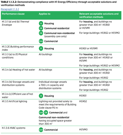
The most significant change affecting the HVAC industry currently is related to the buildings with a Commercial classification.
This included more prescriptive requirements for HVAC system requirements and the reporting required when applying for a building consent.
The intention for the changes is to reduce the energy use of buildings by 40% from the previous Building Code requirements. This will also require a rethink on how we build buildings.
In this article we attempt to provide an overview of the proposed changes. Some of the changes don’t directly affect an installer, but we’ve hopefully covered off the main changes to building construction for commercial buildings and touched upon both glazing and insulation requirements as well.
As always, these changes will add significant cost to the construction of a building when they come into force.
The main change which will affect the HVAC industry is that MBIE have added a whole new section to the H1 stable of acceptable solutions and verification methods, namely NZBC/H1 VM3, which was issued and came in to force immediately – this specifically covers the installation of HVAC systems in buildings and is current now – so the industry is required to meet the minimum requirements listed.
If you are submitting a building consent after November 29th 2021 you will need to meet the requirements of H1/VM3.
For those unfamiliar with the workings of the New Zealand Building Code - it is broken down into sections and our industry jumps across many of the clauses, for example:
- Section C – fire – covering fire dampers, fire stopping, smoke control etc
- Section G4 – ventilation requirements
- Section G10 – Gas Supplies etc
- Section H1 - Energy efficiency
For the November release from MBIE for the new H1 requirements, the following items have been significantly altered in the current versions:
- Significance of Building Classifications
- Climate Zones
- Insulation Values
- Reduction in Window to wall ratios
- Glazing Types
- Floor Types
- Existing Buildings
- Commercial Buildings (New verification method, VM3)
Building Classifications
Building classifications are taken from NZBC Clause A1
- Housing
- Communal Residential
- Communal Non-Residential
- Commercial
- Industrial
- Outbuildings
- Ancillary
Size still matters, buildings with commercial classification smaller than 300m² have tougher requirements than buildings larger than 300m² due to increased insulation requirements.
For Commercial buildings this article will concentrate on the new addition for the NZBC/H1 stable that being NZBC/H1 VM3 and changes to H1 with regards to commercial building insulation and glazing requirements.
Both H1/AS2 and H1/VM3 have effective dates of 29 November 2021 but for H1/AS2 The previous Acceptable Solution H1/AS1 Fourth Edition Amendment 4, can be used till show compliance till 2 November 2022.
H1/VM3 – The new verification method in the stable for Commercial Buildings
Commercial Buildings
All buildings defined as ‘commercial’ require a new type of report (VM3) to prove compliance.
This is concerned with the efficiency of systems, controls, and equipment and does this in each section by providing minimum performance requirements for equipment and components used in HVAC systems that have an impact on energy use.
Most of these requirements are just good engineering, but there is now additional work required to generate a report to prove that the design meets the minimum requirements listed in the verification method (VM3).
We have developed internally a template report covering this below and have altered our internal spreadsheets and schedules to cover off the reporting side. We have also covered off the minimum requirements of the duct and pipe insulation values and items such as duct sealing in our project specifications.
The verification method is assessed in multiple parts and covers the following systems.
- Air conditioning system controls
- Mechanical ventilation system controls
- Fans
- Ductwork insulation and sealing
- Pumps
- Pipework insulation
- Space heating
- Refrigerant chillers
- Unitary air conditioning equipment
- Heat rejection equipment
- Facilities for energy monitoring
- Commissioning requirements
- Maintenance/replacement access
- Maintenance access
Air Conditioning systems Control Requirements
This covers minimum and correct zoning requirements (areas with different heating or cooling needs), having individual thermostatic control, deactivation of air conditioning when the building is not being used, interlocking control operation of units serving the same space, minimum control system dead bands etc.
Floor areas over 1000m² require individual time clock control to set operating times. These requirements of course don’t cover areas that require 24 hr operation such as server rooms and the like.
Outdoor air economy cycles are required to be provided to a building if the air side supply volume of a single piece of air conditioning equipment (roof top package unit, air handling unit etc) exceeds 2500 l/s.
Air conditioning fans suppling over 1000l/s need to be variable speed so the airflow rates can meet demand requirements.
Mechanical Ventilation Control Requirements
Like air conditioning controls the control of the ventilation systems require
- Deactivation; and
- Operating times; and
- Limiting outdoor air flow; and
- Variable speed of fans
All Outdoor air systems require time clock control.
Exhausts systems over 250l/s require time clock control.
The time clock control shall be able to switch the systems on and off at variable preprogramed times and days.
One of the more interesting additions is outdoor air systems supplying over 1000l/s shall have demand-controlled ventilation to the requirements of AS1668:2.
Outdoor air supply volumes are not to exceed more than 20% higher than the minimum NZBC requirements, unless its supplied for “free cooling” or is required to balance extract system(s) – i.e. a kitchen extract system and the toilet extract systems to a fast food outlet as an example.
The other option for exceeding minimum outdoor air requirements is the provision of heat recovery.
Carpark extract systems
All Carpark extract systems are now required to be variable speed, so now need a CO monitoring control system to AS1668:2
Fans
Fans now need to demonstrate that the power input per unit of flow rate don’t exceed minimum performance standards. This differs for 4 different installation types,
- Free inlet free outlet
- Free inlet ducted outlet
- Ducted inlet free outlet
- Ducted inlet and outlet
These requirements do not apply to
- Kitchen extract fans
- Fans in unducted air conditioning units supplying less then 1000l/s e.g Hiwall air conditioning etc
- Smoke spill fans
- Process related fans e.g. dust extract systems
- Fans in systems requiring explosion proof motors
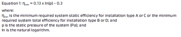
If the static pressure of the system is not more than 200 Pa then a formula is applied to calculate the full load operating point as follows:
For fans over 200 Pa then the following equation applies
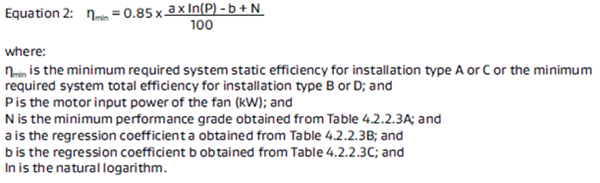
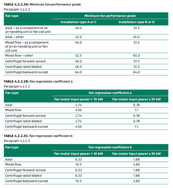
The input requirement is from the following tables
Ductwork requirements
The list here is extensive and we’re not going to list all of the requirements specifically, but ducting is required to be designed to limit the maximum pressure drops to ducting and components.
- The pressure drop in the index run across all straight sections of rigid ductwork and all sections of flexible ductwork must not exceed 1 Pa/m when averaged over the entire length of straight rigid duct and flexible duct. For the purpose of the calculations the flexible duct is considered to be run straight.
- Coils have maximum pressure drops depending on how many rows they are required to be for instance a 4 row coil has a maximum pressure drop of 90 Pa.
- Filters have maximum clean pressure drops depending on its MERV number
- Intake Louvres now have maximum pressure drops dependant on louvre type – e.g a single stage louvre maximum pressure drop is 30 Pa
- Total amount of flexible duct in a single run is limited to 6 meters
- VAV boxes now have maximum pressure drops e.g a VAV box with electric reheat is maximum pressure drop of 100 Pa with the damper fully open
- Duct elbows and bends have requirements for the provision of either radius bends or provided with turning vanes.
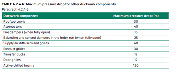
Ductwork components also now have maximum pressure drops as noted below
Ductwork insulation and sealing
NZBC H1/VM3 now has requirements for the provision of insulation to ducting systems and an extensive list of where these do not apply. These are significantly above current industry standards.
Duct insulation is not required where the ducting is run exposed in the space and surfaces wont drop below dew point. But recommend the exclusions are read so the reader is clear on requirements.
Flexible ducting now requires a minimum insulation R value of 1.0 m²K/W so the industry typical 25mm insulated flexible duct will no longer cut the mustard.
Ductwork and fittings require to have the minimum insulation R values as per table 5.2.1.1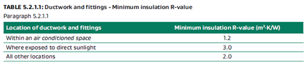
Ducts are also required to be sealed to the requirements of AS4254.1 and part 2 as per the system pressure class.
Pumps and piping
VM3 encourages the input power to pumps to be minimised when installed as part of HVAC system.
It does this by specifying minimum pump motor efficiencies and averaged maximum pipe pressure drops depending on pipe size pump operating condition (fixed or variable flow) and operating hours.
All these numbers are reasonable and from a design standpoint represent good practice.
This also encourages the use of variable speed pumping on the distribution side by having higher allowable pipe pressure drops.
When selecting a pump request from the supplier confirmation the pump will meet the energy efficiency index (EEI) to H1/VM3 which is dependent on rated hydraulic power and pump motor size.
Piping, vessels, heat exchangers and tanks insulation
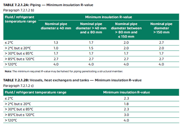
Minimum piping insulation R-values are now required complying with AS/NZS 4859.1 and is dependent on the nominal operating temperatures of the system and pipe nominal diameter. Don’t forget about vapour barriers in cooling systems. Again these are higher than current industry standards for instance a Ø100 nominal chilled water pipe with a temperature range of 6-12°C would require R2.0 insulation – using Armaflex FRV insulation as an example would require 50mm insulation. Increasing pipe insulation thickness can become a losing battle as the increase in surface area to the external surface can increase the heat loss so this should be looked at as part of the analysis.
Space heating
Again, efficient use of depletable resources are encouraged when proving space heating either directly or indirectly to a space – At this stage H1/VM3 basically encourages the efficient use of gas, electricity or biomass or combination of the energy source and also the provision of renewable sources such as solar.
Gas boilers are required to have a minimum gross thermal efficiency of 90% under normal operating conditions.
Refrigerant Chillers
All chillers supplied in New Zealand are required to meet the minimum energy performance standards (MEPS) and this is reflected in H1/VM3.
The additional requirement under H1/VM3 is the prevision of additional energy efficiency ratio requirements. These requirements only apply to refrigerant chillers that form part of an air conditioning system. The ratios are based on the type of chiller and two options are provided for providing for chillers with lower full load COP’s but higher integrated part load efficiency verses high full load COP but lower integrated part load efficiency - Wr/W input power ratios and the integrated part load Wr/W input power
Unitary Air Conditioning Equipment
All heat pumps, like chillers supplied in New Zealand are required to meet the minimum energy performance standards (MEPS) and this is again reflected in H1/VM3 but for plant and equipment over 65 kW (kW of refrigeration) the equipment has to comply with additional energy efficiency ratio of – input power includes both the compressor and fan input power.
-
4.0 Wr/W input power water cooled
-
2.9 Wr/W input power Air cooled
Heat rejection equipment
Cooling towers, air cooled condensers, dry coolers and evaporative condensers have requirements to ensure equipment does not exceed maximum allowable fan motor input power. This does not apply to chillers which are noted elsewhere in H1/VM3.
Air cooled condensers are limited to 42W of fan motor power for each kWR of heat rejection (kW of Refrigeration)
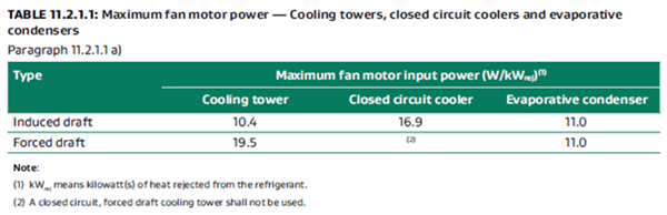
Cooling towers, evaporative coolers and closed-circuit coolers must meet the following fan motor input power ratios
Energy Monitoring
VM3 requires energy to be monitored so that excessive energy use is detected
The requirements are in two stages depending on building size.
For building 500m² to 2500m² there is a requirement to monitor HVAC energy use with time of use consumption of gas and electricity.
For larger buildings over 2500m² the requirements are more complex where energy use is monitored on air conditioning plant items including the individual time of use consumption of
- Cooling plant
- Heating plant
- Air handling fans
The energy use is required to be recorded in an integrated single location (say included in a BMS system) to allow analysis and review – its required that a minimum period of 12 months of data is retained at any one time for this purpose.
Maintenance Access
VM3 requires sufficient access to all plant and equipment is provided for commissioning, maintenance and replacement of equipment provided.
Increase requirements to Commercial building insulation value to building elements and Glazing
Like their domestic cousins Commercial building construction R values have also had a significant makeover with the addition of H1/AS2 covering building over 300m². These requirements are current now, but the previous version H1/AS1 version 4 can be used up to 3 November 2022 for compliance.
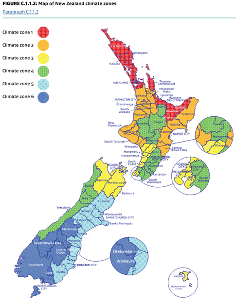
Increased number of Climate Zones
There are now 6 climate zones increasing from three in the previous versions reflecting the differing areas of the country from the tropical north to the cooler south - Each climate zone has different building and glass insulation requirements
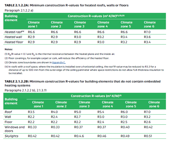
Insulation Values
This is where the major changes to the construction of a building have changed.
The minimum required insulation values have drastically increased.
Glazing R values have increased in domestic buildings from nothing to a minimum of R0.33 to a maximum of R0.42 depending on climate zone.
This will have the largest cost effect on commercial buildings.
Expected knock on effects for us in the HVAC industries will include
- Thicker walls/roof cavity
- Less steel frame wall constructions
- Less cavity space for services
- Affected AC System design
Note these only cover the building insulation values – solar control on glazing is one of the biggest contributors to air conditioning system sizing and is not covered in the new documentation. Glass shading coefficients are addressed in the calculation method for solar aperture, but the glazing shading coefficients have a major impact on the air conditioning loads and building energy use. This is a weakness in the current edition of the documentation.
Conclusion
The new requirements will have an impact on building energy use but as engineers we need to strive further and remember that these requirements are the minimum standards and consolidate what we would consider to be good practice. We can always do better.
As HVAC engineers we design systems and its just as important to meet these requirements and have the whole system working correctly and each component interacting as part of that system.
Systems also need to be maintained to a good standard and able to be replaced when needed and everyone from the designers to the original HVAC contractor to the maintenance contractor has a hand in ensuring this can done safely and easily.
The Authors:

22 DEGREES
LinkedIn

22 DEGREES
LinkedIn